As for the power supply which the voltage doubler rectifier is installed in, input voltage is rectified by voltage doubler circuit when the change-over terminal of AC100/200V is set at AC100V. On the contrary, when the changeover terminal is set at AC200V, input voltage is rectified full wave rectifier circuit.
Below shows operation tutorial of voltage doubler rectifier circuit.
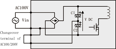
Fig.1 Voltage doubler rectifier circuit
The voltage doubler rectifier circuit as shown in Fig.1 and circuit loop is different between positive voltage and negative voltage.
When input voltage is positive, circuit as shown in Fig.2 will operate and charge C1. On the contrary, when input voltage is negative, circuit as shown in Fig.3 will operate and charge C2.
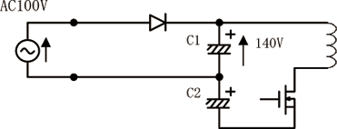
Fig.2 Circuit loop when input voltage is positive
Therefore, V-DC, voltage of C1 + C2, will always fix at DC280V in either case of AC100V or AC200V, and the voltage inside of the power supply will be retained at a constant level.
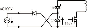
Fig.3 Circuit loop when input voltage is negative
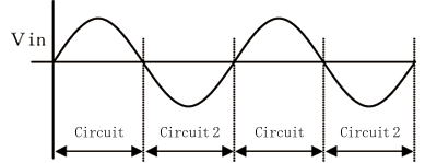
Fig.4 Timing of circuit changeover
Technical Product-related Inquires
e-mail:support@cosel.co.jp